Structured multi level automation with integrated safety interlocks and direction control logic.


![[background image] image of plumbing blueprints (for a plumbing service)](https://cdn.prod.website-files.com/image-generation-assets/fb45a4ce-430e-4843-8f2b-6e776ff01caf.avif)
The project describes the control of a four-level industrial lift operated by a PLC.
Each station can be selected via push buttons, and the system automatically determines the required direction based on the current position. Position feedback is provided through end switches installed at each station.
These signals are used to stop the lift precisely and to update the position status. The control system enables automated travel between the selected target stations while ensuring that movement is only permitted under valid operating conditions.
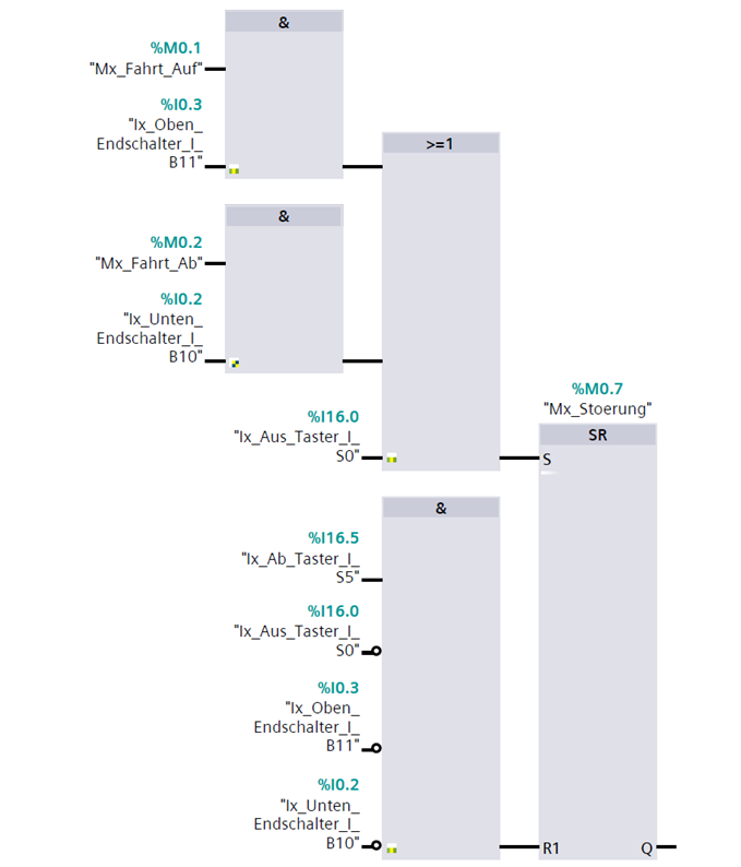
The control program is structured into six clearly separated networks within Siemens TIA Portal. Network 1 handles safety supervision, including monitoring of the stop button, upper and lower safety limit switches, and prevention of simultaneous upward and downward movement.
If an invalid condition is detected, a fault bit is set and all motion commands are blocked. Target selection is processed in Network 2 using stored target bits and timer-based signal stabilization.
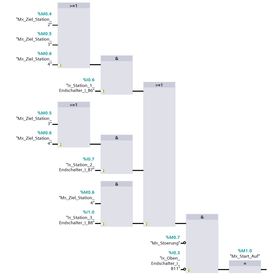
Network 4 determines the required direction based on the current position and selected target.
Set/Reset logic in Network 5 manages the motion flags while ensuring mutual locking between upward and downward travel. Motor outputs are controlled in Network 6 and are only enabled if no safety condition is violated.
The complete control logic was implemented in Siemens TIA Portal using Function Block Diagram (FBD). System behavior was validated using PLCSIM simulation.
Functional testing included verification of:
– Correct direction selection
– Target storage and reset logic
– End switch response
– Safety interlock activation
– Mutual exclusion of movement directions During testing, issues related to simultaneous direction activation were identified and resolved through additional logical conditions. The final system operates deterministically and ful fills all defined functional and safety requirements.
The lift operation follows a clearly structured control sequence from input processing to controlled movement execution.User inputs such as start, stop, and station selection are evaluated within the PLC.
Before any motion is enabled, all safety conditions and interlocks are verified to ensure safe system behavior.Based on the current position and selected target, the control logic determines the required direction and activates the corresponding movement.
During operation, position feedback from end switches is continuously monitored.
This ensures precise stopping at each station while preventing conflicting motion commands through mutual locking of movement directions.
The developed PLC control system provides reliable and structured operation of a multi-level lift.
The implementation demonstrates clear logic design, safe motion control, and consistent system behavior under defined operating conditions.
The project highlights the importance of structured programming, safety interlocks, and simulation-based validation in industrial automation.
“Reliable automation is achieved through clear logic design, controlled processes, and a strong focus on system safety.”
![[headshot] image of customer (for a medical clinic)](https://cdn.prod.website-files.com/6939820137731e8b0f661575/694a8426a800feaab92a07fc_3FMU1876_Biasio_klein.jpg)